1. Introduction: Beyond the Spec Sheet – Why Hardware Teardowns Matter
In the B2B commercial kitchen equipment sector, relying solely on marketing spec sheets can be risky. While exterior wattage ratings offer a surface-level idea of performance, they fail to reveal how an appliance will perform during continuous peak-hour service. For commercial procurement teams, distributors, and appliance engineers, conducting a thorough hardware teardown is the most effective way to evaluate long-term reliability and build quality.
Analyzing internal components—such as motor winding materials, printed circuit boards (PCB), safety interlock mechanisms, and thermal overload protections—provides the clear data needed to estimate maintenance cycles, failure rates, and total cost of ownership (TCO).
2. Motor Engineering Comparison: Analyzing the XKH-9845 vs. XKH-9535 Stator Coils
The electric motor serves as the core powerhouse of any commercial food prep system. During heavy-duty blending, the motor experiences rapid thermal spikes and continuous mechanical resistance. A teardown reveals the difference between industrial-grade components and cost-cut alternatives.
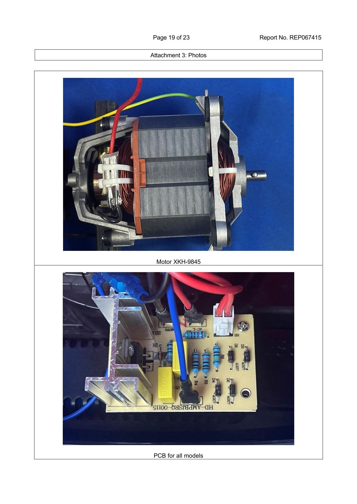
Key motor engineering benchmarks observed in heavy-duty commercial builds include:
- Stator & Rotor Winding Material: High-grade commercial motors utilize 100% pure copper wire rather than copper-clad aluminum (CCA). Copper offers superior electrical conductivity and thermal resistance under sustained load.
- Stator Stack Thickness: Comparing models like the high-torque XKH-9845 against the standard XKH-9535 shows that thicker lamination stacks provide higher magnetic flux efficiency, delivering consistent torque without excessive heat buildup.
3. PCB Control Board Teardown: Voltage Regulation and Component Soldering Quality
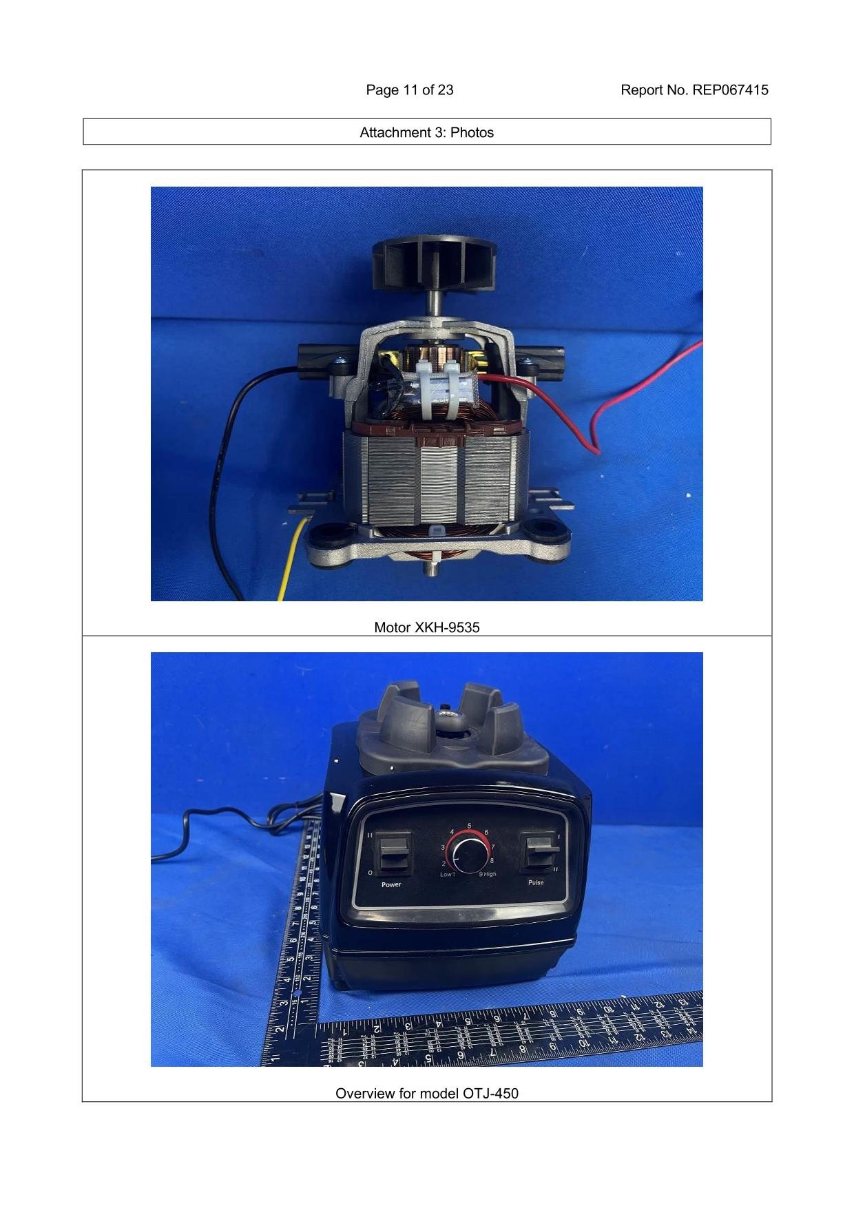
The control board acts as the central brain of the machine, regulating motor speeds and managing electrical current during initial torque surges. A close inspection of the PCB reveals the unit’s ability to handle line voltage fluctuations.

Evaluating PCB manufacturing quality involves inspecting several key features:
- Component Rating & Layout: Industrial control boards use high-temperature capacitors, solid-state relays, and flame-retardant substrate materials designed to resist continuous heat.
- Solder Joint Integrity: The underside of the board should display clean, wave-soldered traces with reinforced solder joints to prevent component displacement caused by high-RPM chassis vibration.
4. Safety Interlock Switches: Protecting Operators from High-RPM Hazards
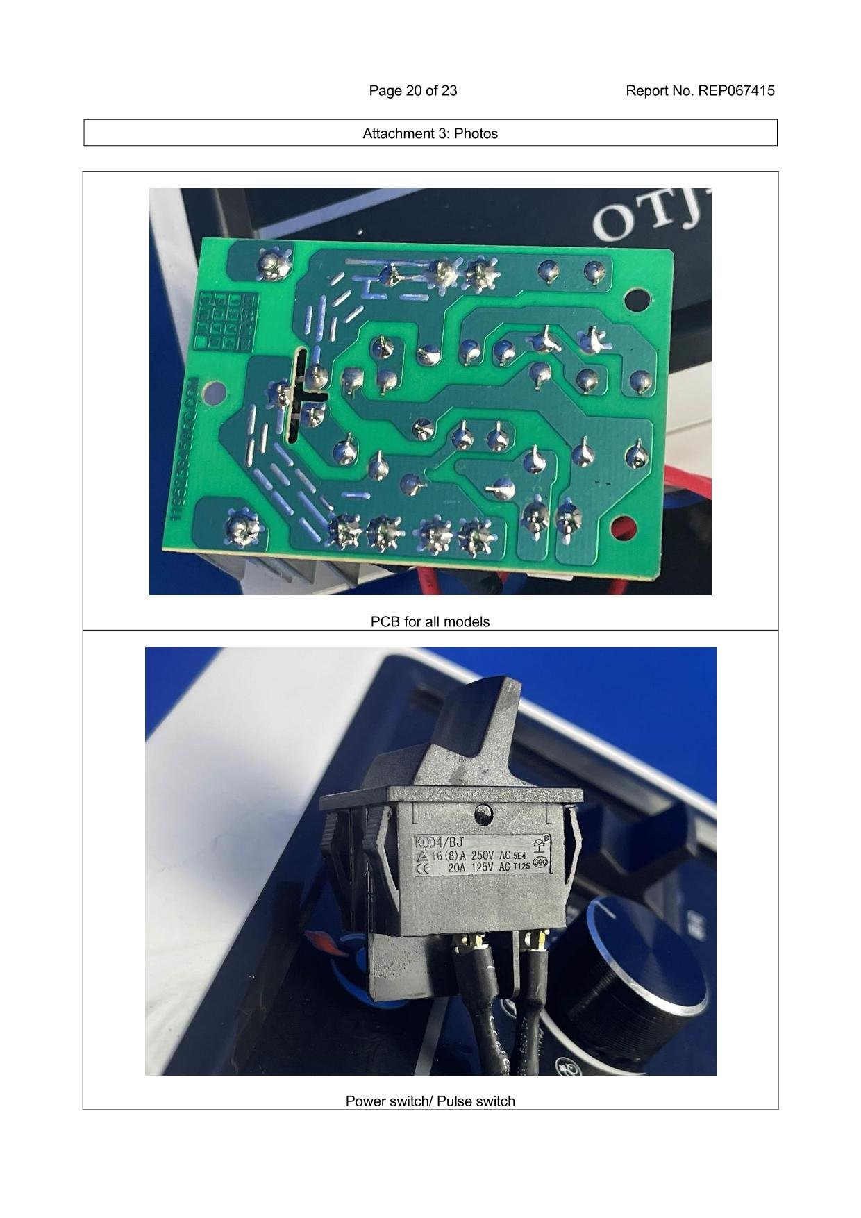
Safety compliance standards like IEC 60335-2-14 require electric food preparation equipment to prevent accidental blade engagement. This protection is driven by mechanical micro-switches installed in the motor base.
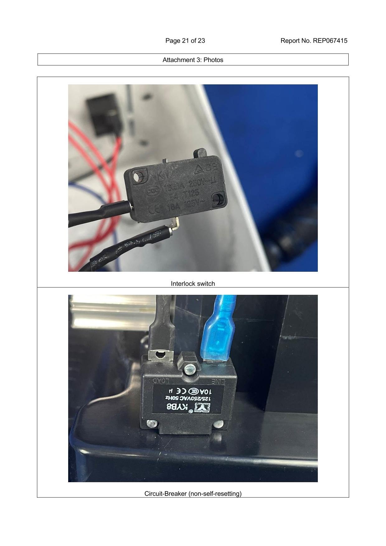
When the blending container is placed onto the motor base, a physical actuator presses down on the interlock micro-switch, closing the electrical circuit. If the jar is removed or improperly seated during high-speed operation, the switch instantly interrupts power to the motor, preventing operator injury and drive socket gear stripping.
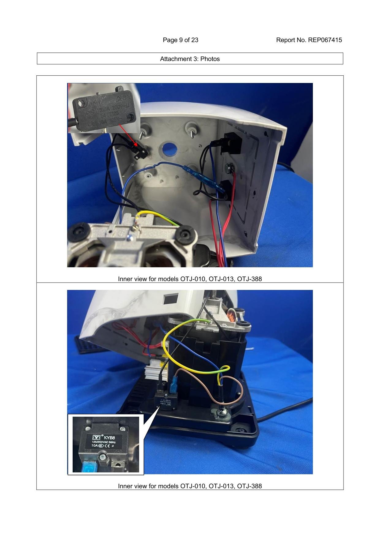
5. Overload Protection Systems: Manual Reset Circuit Breakers vs. Thermal Fuses
When heavy ice loads or thick mixtures stall the blade assembly, the motor draws excessive current, rapidly generating internal heat. Without protection, this thermal surge can permanently melt motor insulation.

Unlike single-use thermal fuses that require complete component replacement after a power trip, commercial blenders integrate a manual-reset circuit breaker. If an overload occurs, the push-button trips outward to cut power. Once the motor cools down and the blockage is cleared, kitchen personnel can press the exterior button to resume operation, cutting down equipment downtime.
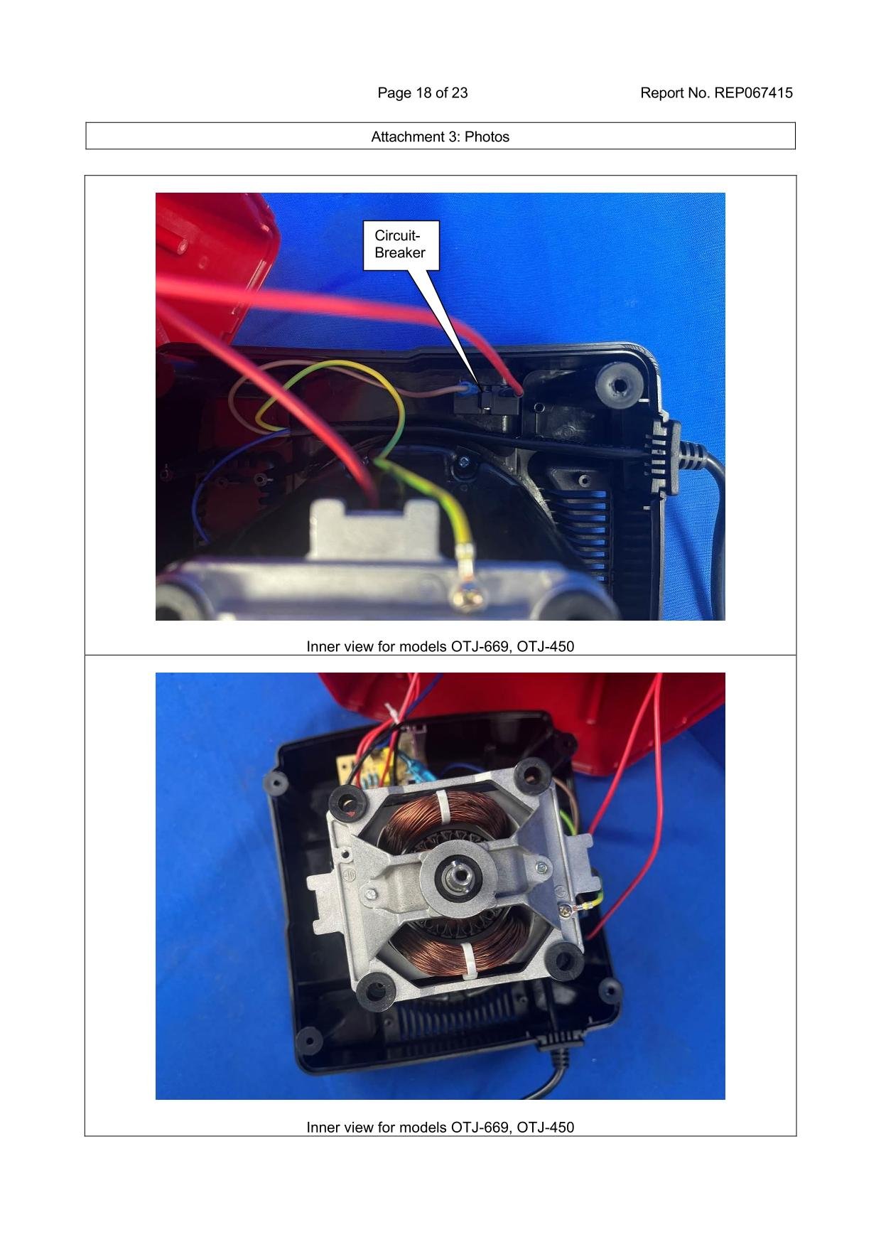
6. Chassis Grounding & Electrical Safety: Mitigating Leakage Hazards in Wet Kitchens
Commercial kitchens are wet, high-intensity environments. Ensuring proper chassis grounding and liquid ingress protection is critical for passing international electrical safety audits.
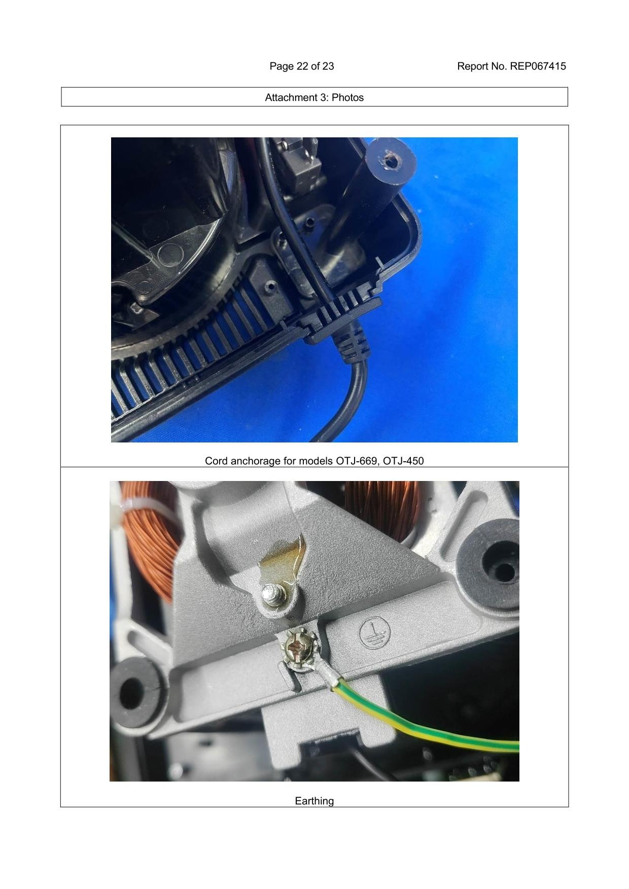
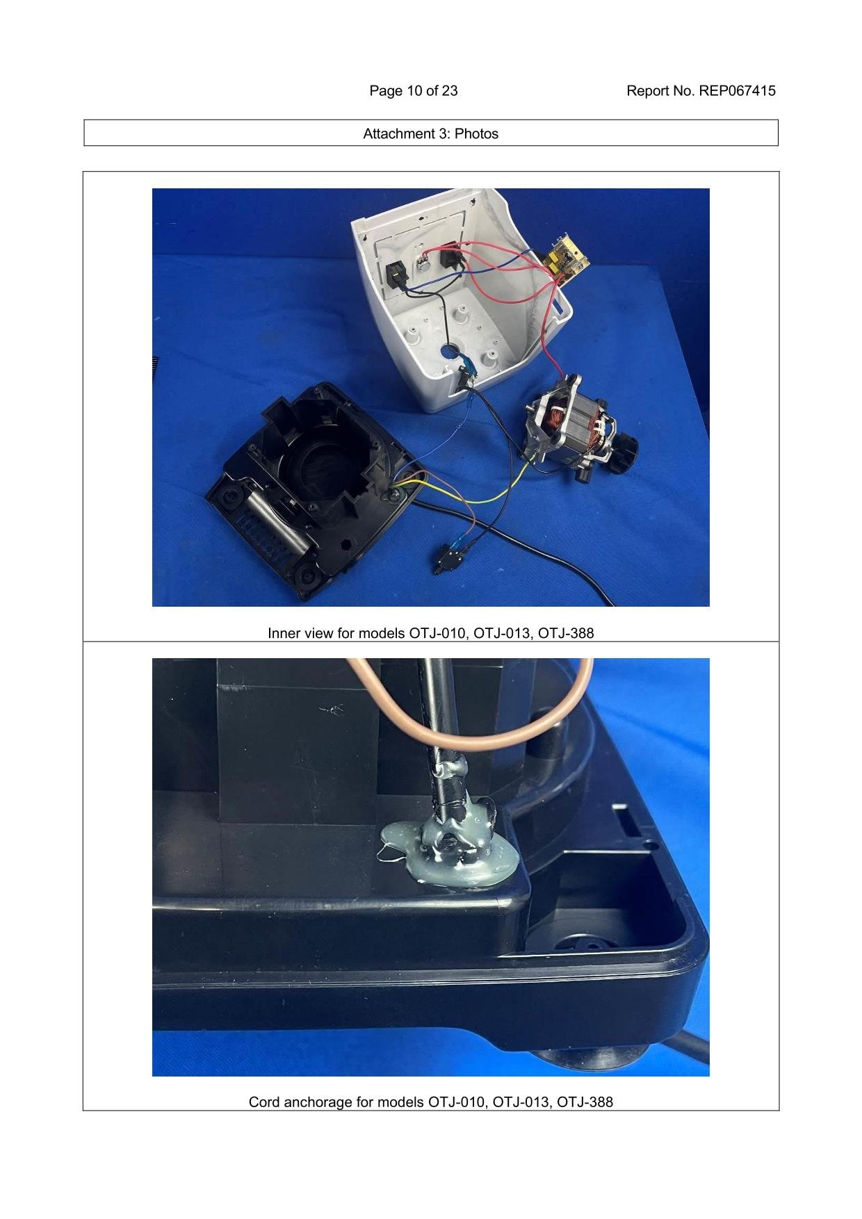
During our teardown, two critical safety features were highlighted:
- Direct Frame Grounding: A dedicated earthing conductor is bolted directly to the metal stator housing, safely channeling any stray leakage current to the ground pin.
- Strain Relief Cord Anchorage: The power cord entrance is secured with a heavy-duty mechanical clamp and waterproof sealant to prevent wires from pulling loose or admitting moisture into the motor compartment.
7. Mechanical Switches vs. Potentiometers: Ergonomics & Waterproof Longevity
Control panels undergo thousands of actuations over their operational lifespan. Choosing between mechanical toggle switches and electronic potentiometers depends on the specific workflow requirements of the establishment.
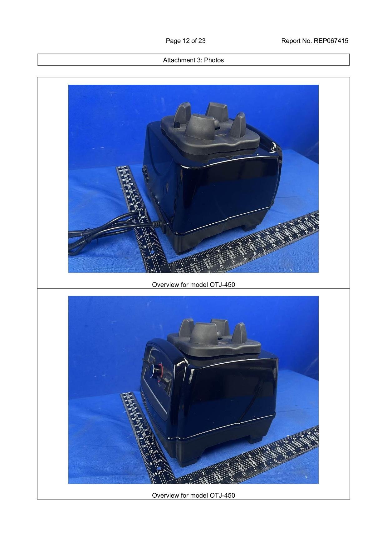
Heavy-duty mechanical toggle switches are often preferred in high-volume environments for their positive tactile feedback and durable internal contact points. When paired with protective rubber boots, they provide clear liquid ingress protection against accidental spills.
8. Transmission Engineering: Stainless Steel Drive Sockets & Shock Absorption Pads
The drive socket (mushroom head) serves as the primary mechanical interface between the motor shaft and the blade assembly, bearing the full brunt of torque forces during high-speed startups.
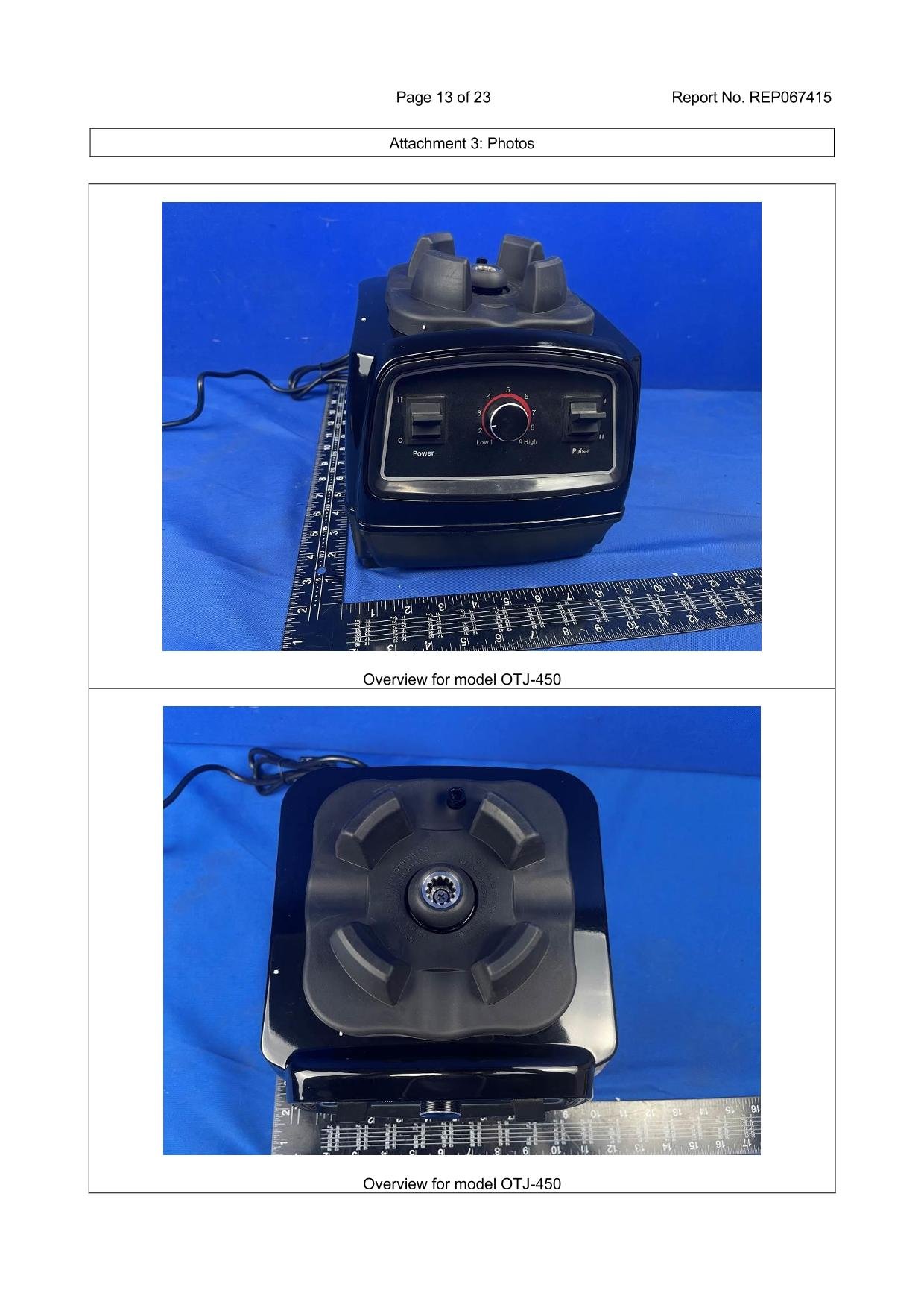
High-quality commercial builds feature precision-machined stainless steel or zinc-alloy drive teeth fixed over a splined steel motor shaft. Surrounding the drive socket is a heavy rubber pad that absorbs operational vibrations, dampens acoustic noise, and protects the motor housing from spilled liquids.
9. B2B Sourcing Summary: How to Evaluate OEM/ODM Internal Build Quality
For procurement managers conducting pre-shipment sample evaluations or factory audits, use this checklist during product teardowns to confirm internal quality:
- Inspect motor windings to verify pure copper construction instead of copper-clad aluminum wire.
- Verify the presence of a manual reset circuit breaker rather than a single-use thermal fuse.
- Check that safety interlock switches feature dust and moisture protection ratings.
- Confirm that the drive socket uses stainless steel gear teeth rather than plastic engagement teeth.
- Check that internal wire bundles are bound, routed cleanly away from hot components, and fitted with flame-retardant insulating sleeves.